
Routing Offset Toolpaths

Create a toolpath that runs either inside or outside of a closed contour. The toolpath is offset from the contour by the tool radius to the edge of the cut surface will align with the contour perimeter.
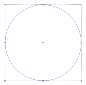
![]()
If a cutting tool cannot follow the contour shape into a tight corner or curve, the toolpath will follow the closest smooth curve possible.
Activating the Routing Offset tool will open the strategy dialogue. Use the Strategy Dialogue to add and remove cuts.
Set the Cut Parameters for each cut to define how the Routing Offset will be generated.
Steps
-
Select the contour for the toolpath to follow
-
Activate the Routing Offset command
-
In the Routing Offset dialogue, select the desired tool from the Tools list and select Add Tool
The Sort by list sorts the Tools list by parameter or tool typeThe first tool in the list is always defined as the Rough tool, and is typically the main cutting tool. Additional tools serve as the Clean or Fine tools -
Define a Depth for the selected tool in the tool listing window
-
Add additional cuts using other tools as necessary
-
Set the Routing Offset Parameters
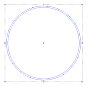
External (Male) When checked, the toolpaths will follow the outside of the contour Internal (Female) When checked, the toolpaths will follow the inside of the contour Weld Offsets When checked, overlapping offsets will be welded together to form a single toolpath group. If unchecked, overlapping offsets will remain unchanged Sharp Corners Offset toolpaths from square corners are rounded by default, allowing for smoother machine operation without rounding the contour perimeter. When checked, this parameter forces toolpaths to be generated with square corners. It is generally not recommended to enable this paramter. Inlay If checked, the toolpath defines either the socket for an inlaid piece of a different material (if the toolpath is set to Internal), or the cut that will separate the inlay itself from the plate (if the toolpath is set to External).
Because a round bit is being used to cut out both pieces, both the male and female toolpaths need to take into account the dimension of the tool. This changes the shape of the toolpath, particularly in corners.If this option is checked, the Inlay Gap parameter displays. This parameter indicates the size of the gap that will exist between the inlay and its socket.
Bridges When checked, generated toolpaths will leave small tabs of material uncut to connect the design to the remaining material sheet. Additional parameters are activated to define the bridge shape when this option is checked. -
Click OK
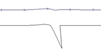
Bridges
Bridges are lifts in Routing Offset toolpaths that create tabs that maintain the connection between part being cut and the material it is being cut from. Bridges improve stability so the part does not move while being cut. The tabs are trimmed away after cutting the part.
Bridge Parameters
| Type | Define the shape of the bridge. Each shape has advantages for different materials, while smooth bridges allow for the smooth machine operation |
| Length | Length of each bridge. Longer bridges have increased strength, shorter bridges work well in stronger materials |
| Height | Height of each bridge tab. Another parameter to influence bridge strength |
| By Number | Define the number of bridges in an offset |
| By Length | Define the distance between each bridge |
| Manual | Define specific bridge locations along the offset. |
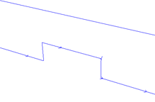
Bridge Shapes
| Lift |
|
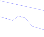
| Ramp |
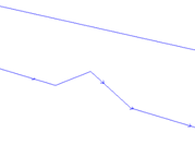
|
| Smooth |
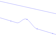
|
| Ramp Mesa |
|
| Smooth Mesa |

|